


Metallography
Metallography is an important tool for quality assurance and damage analysis.
As part of these tasks, TAZ GmbH tests the microstructures of metallic materials of all kinds. Trained metallographers and materials engineers at TAZ GmbH take care of your application.
For a metallographic examination, representative sections are taken from the component to be examined. We have a wide range of saws and cutting machines, including low-speed saws, at our disposal to ensure gentle sampling for the respective material. The preparatory work steps also include embedding in a plastic mass. This enables a sample preparation with sharp edges. In order to optimize the edge sharpness of hard-to-prepare, surface-hardened samples, the sections are supported with a special aluminum foil before embedding or even nickel-plated in our electroplating system. With two hot embedding presses, several cold embedding options and a UV embedding lamp, we have all the options for embedding raw material, hardened gears and even the finest electronic components at our disposal for embedding. So that the sample can finally be examined under the light microscope, a high surface quality without grooves and scratches is a prerequisite. We achieve this with our manual and semi-automatic grinding and polishing machines from Buehler and Struers and with our application-dependent variety of different grinding wheels, sandpaper, polishing cloths and the associated lubricants and suspensions.
We have a number of microscopes from well-known manufacturers such as Zeiss and Keyence at our disposal for assessing the microscopic structures. We do our work e.g. B. with stereo microscopes, confocal reflected light microscopes, laser scanning microscopes (LSM) or scanning electron microscopes (SEM). Due to the different reflection properties of metals and non-metals, first statements about the purity of the material are possible immediately after polishing. TAZ GmbH tests the degree of purity of metals according to ASTM E45 or DIN EN 10247. The examination for edge oxidation or material separations, such as hot cracks, cold cracks, gaps, pores, slag inclusions, etc. is preferred in the polished state due to the better contrast carried out.
Metallography cast structure

The formation of graphite can be seen in the metallographic section even in the unetched state. Contrasting is also necessary to display the microstructure matrix.
Metallography – Crack
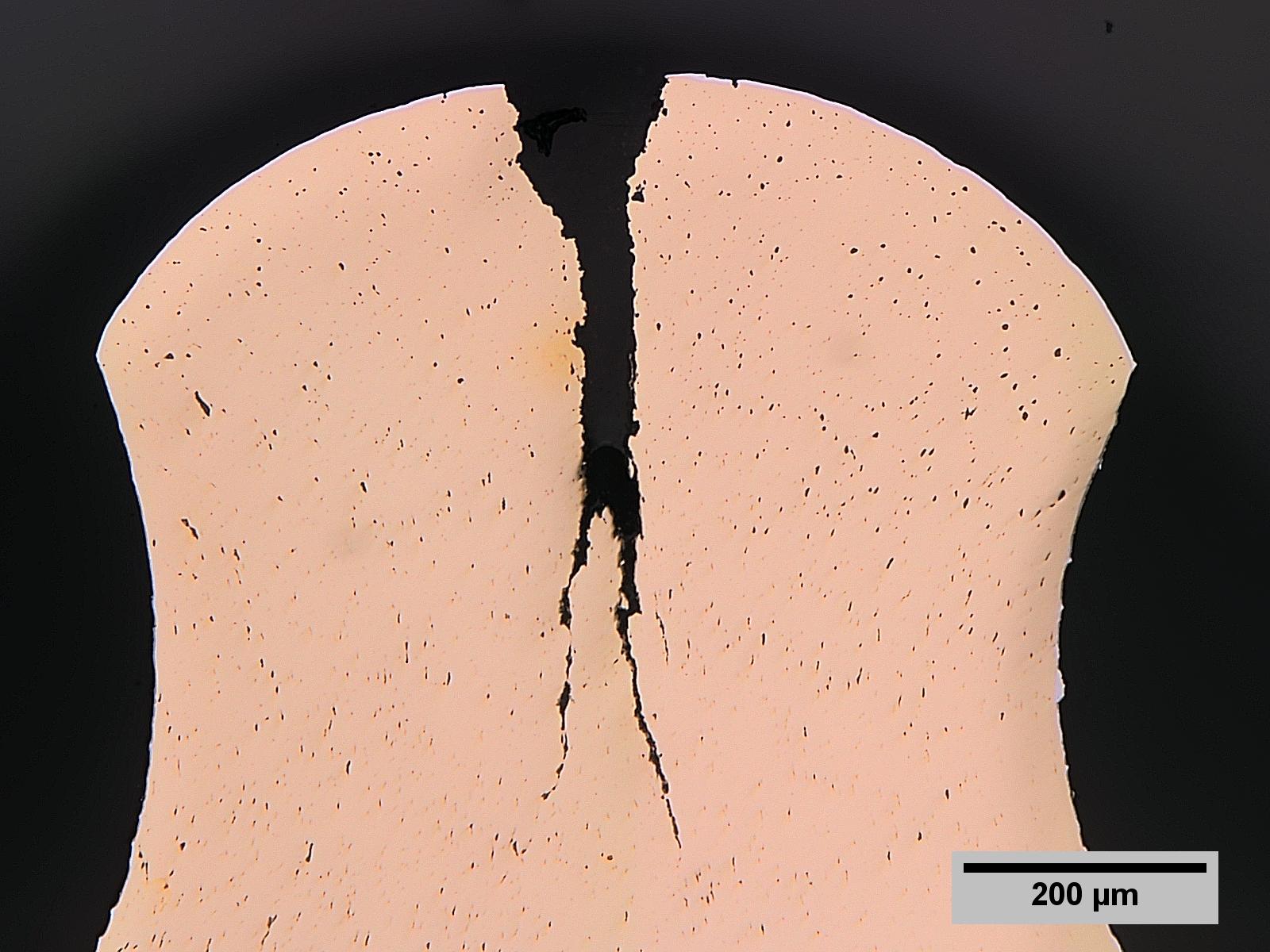
Structural inhomogeneities such as pores, overlaps or cracks (image) can be better displayed in the unetched section due to the better contrast ratio.
Various etching effects can be created by contrasting metallographic sections with suitable etchants. If the structure is correctly contrasted, statements can be made, e.g. B. about the heat treatment condition (hardened, soft annealed, normalized, …) and the quality (carbon content), as well as in many cases conclusions about the manufacturing process (drawn, rolled, cast, …) and causes of failure in cases of damage (grain boundary cementite, coarse grain formation, …) draw. With a suitable etching solution, the former austenite grain boundaries can even be shown in hardened, martensitic components. Using special software, TAZ GmbH can not only determine the average grain size, but also graphically display the distribution of the grain sizes. Any edge decarburization or the course of weld seams including the heat-affected zone (HAZ) can also be made visible by etching.
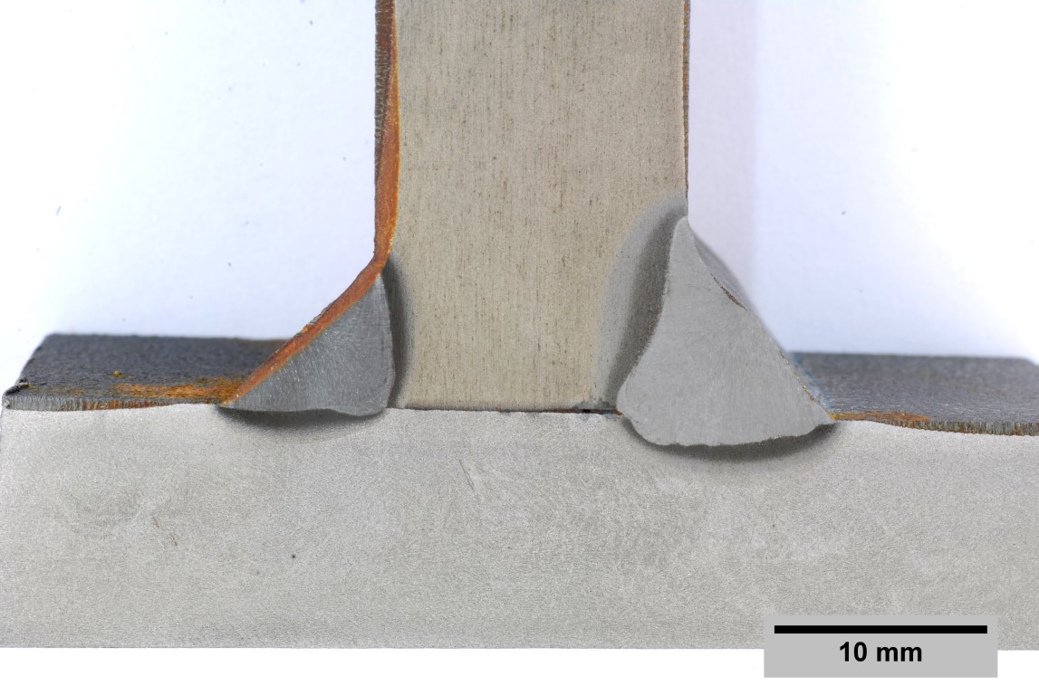
Metallography macro section
Metallographic microsection

Metallography Austenite Grain Boundaries
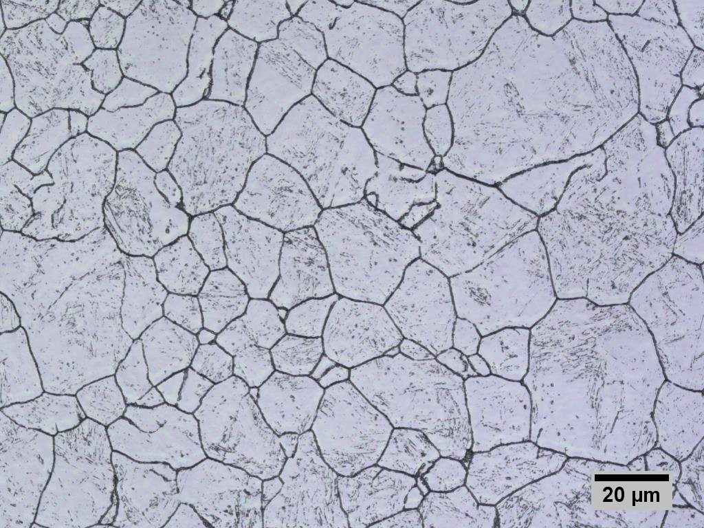
With the help of our wide range of etching solutions, we can display the microscopic microstructures of almost all metals. Also special etchings, e.g. B. the representation of the former austenite grain boundaries in components that have already been tempered do not pose any problems for our metallographers.
With our regularly calibrated microscopes, we can not only measure layer thicknesses, but also customer-specific measuring tasks, such as B. take on welds. It doesn’t matter whether thicknesses, lengths, radii, diameters, tangential distances, areas, porosity or angles are to be measured.
Geometric measurement of an ultrasonic seam
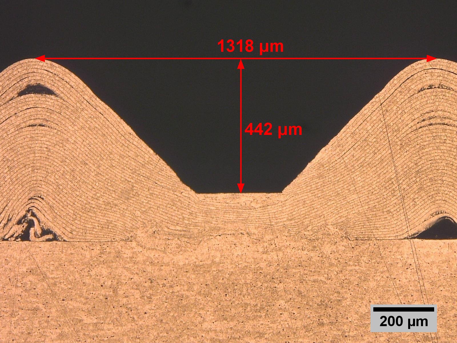
With our digital image evaluation methods, we can easily measure layer thicknesses or distances, as shown in the example of the ultrasonic welded joint. Radii, diameters or angles can also be reliably measured.
ASTM E45 – Standard Test Methods for Determining the Inclusion Content of Steel
ASTM E112 – Standard Test Methods for Determining Average Grain Size
ASMT E340 – Standard Practice for Macroetching Metals and Alloys
ASTM E381 – Standard Method of Maroetch Testing steel bars, billets, blooms and forgings
ASMT E407 – Standard Practice for Microetching Metals and Alloys
DIN EN ISO 643 – Mikrophotographische Bestimmung der erkennbaren Korngröße
DIN EN ISO 945 – Bestimmung der Mikrostruktur von Gusseisen – Graphitklassifizierung durch visuelle Auswertung
DIN EN ISO 1463 – Metall- und Oxidschichten – Schichtdickenmessung
DIN EN ISO 2624 – Kupfer- und Kupferknetlegierungen – Bestimmung der mittleren Korngröße
DIN EN ISO 3887 – Stahl – Bestimmung der Entkohlungstiefe
ISO 4967 – Steel – Determination of content of nonmetallic inclusions – micrographic method using standard diagrams
DIN EN 1024 – Metallographische Prüfung des Gehaltes nichtmetallischer Einschlüsse in Stählen mit Bildreihen
und viele mehr…
Case studies
Cracks were found on aluminum cast components made of the material EN AC-43000 (AlSi10Mg(a)). These cracks were corrected with a repair weld. To avoid stress peaks caused by welding, the component was then solution annealed again and aged hot. As part of a material analysis quality control in the laboratory of TAZ GmbH, it should be validated whether the repair process is acceptable for the customer. For this purpose, the corresponding areas should be prepared metallographically and documented with the light microscope or the laser scanning microscope. The metallographic section sample was contrasted for a better representation of the weld seam and the microscopic structure. The common pickling solution according to Keller was slightly modified and optimized by our metallographer. The weld seam was first shown macroscopically. It can be seen that welding was done from both sides. Since several weld nuggets can be detected, a multi-layer weld seam can be assumed. At low magnification, significantly finer dendrites can be seen in the weld compared to the base material.
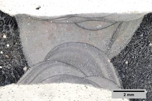
Anomalies were then documented in detail. Above all, small gas pores can be detected in the welding zone.
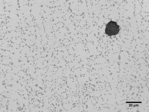
After the macroscopic examination, the microstructure was documented in the laser scanning microscope. The welding filler material used shows a near-eutectic, homogeneous structure with a dendritic alpha phase and a moulded, refined eutectic. The refinement can be recognized by the formed, spheroidal particles in the eutectic, which would appear elongated and needle-like without heat treatment.
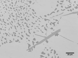
The base material shows a similar picture. Here, too, a dendritic alpha phase and a moulded-in, refined eutectic can be seen, but there are also elongated AlFeSi phases. This suggests a slightly different chemical composition between the base material and the filler material.
The micrographs were also checked with a hardness test. For this purpose, a linear hardness curve was drawn up from the base material via the center of the weld seam to the opposite base material and the hardness profile was shown graphically. It can be seen that the filler metal is about 50 HV softer than the base material. The conspicuously low hardness value at 15 mm is probably due to a gas pore that happened to be hit exactly.
Conclusion: The microstructure and the hardness values indicate that the solution annealing was carried out correctly after the repair welding. The increased hardness of the base material also indicates (hot) aging. Because the hardness is significantly lower and no elongated AlFeSi phase can be found, it can be assumed that a different material was selected as the welding filler material.